 PRODUCT
Slotted Countersunk Machine Screw DIN 963 Steel Stainless Steel and Brass Fastener for Equipment Panels Furniture Hardware and General Assembly
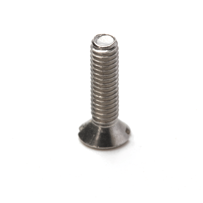
DIN 963 Slotted Countersunk Machine Screws feature a countersunk head, a straight slot drive and a metric machine thread for flush assembly. The DIN 963:1990 reference includes steel, stainless steel and brass materials, with reference thread sizes from M1 to M20. Send your required material, thread size, overall length and quantity for a quotation.
- Standard Reference
- DIN 963:1990
- Product Grade
- A
Product Details
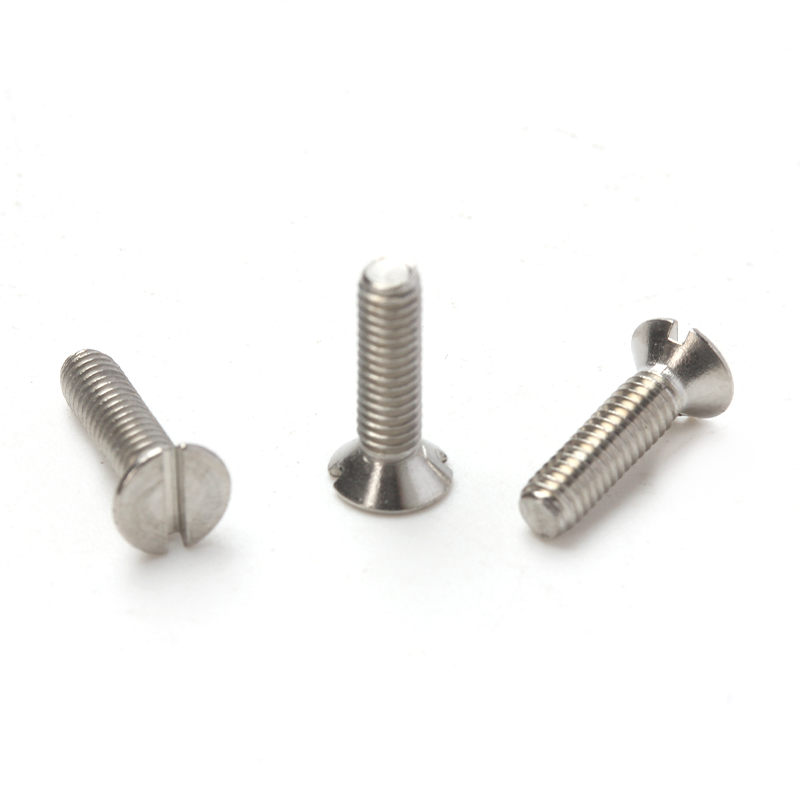
A DIN 963 Slotted Countersunk Machine Screw combines a flat countersunk head with a single straight slot. The head seats within a matching countersink, allowing a flush surface when the screw and recess fit correctly. A flat-blade screwdriver engages the slot for installation and removal.
The metric machine thread connects to a compatible tapped hole or matching nut. This makes the screw a fastening option for equipment panels, furniture fittings and general mechanical assemblies designed for countersunk machine screws.
For replacement orders, identify the original standard, thread, overall length and material requirements. Head appearance alone does not establish interchangeability with a tapping screw, wood screw or another countersunk screw standard.
Product Specifications
| Item | Details |
|---|---|
| Product Name | Slotted Countersunk Machine Screw |
| Standard Reference | DIN 963:1990 |
| Head Type | Flat Countersunk Head |
| Drive Type | Straight Slot |
| Thread Type | Metric Coarse Machine Thread |
| Thread Diameter — Standard Reference | M1–M20; see dimensional table below |
| Materials in the Standard Reference | Steel, Stainless Steel, Brass / Copper-Zinc Alloy |
| Product Grade | A — dimensional tolerance grade |
| Nominal Screw Length l | Overall length, including the countersunk head |
| Material Grade and Surface Finish | State requirements with the inquiry |
| Assembly Requirements | Matching countersink and compatible internal thread or nut |
The tables below provide standard reference information. Availability is confirmed for the requested material, diameter, length, mechanical requirements and finish combination.
Material and Mechanical Requirements
| Material Group | Classes or Designations in the DIN 963:1990 Reference | Referenced Mechanical Standard |
|---|---|---|
| Steel | 4.8, 5.8, 8.8 | DIN ISO 898-1 |
| Stainless Steel | A2-70, A4-70 | DIN 267-11 |
| Brass / Copper-Zinc Alloy — CuZn | CU2 or CU3, selected by the manufacturer | DIN 267-18 |
Product Grade A describes dimensional tolerances; it is different from a mechanical property class. CU2 and CU3 are copper-alloy designations, not steel property classes.
DIN 963 Standard Reference Dimensions
All dimensions are in millimeters.
| Thread Size d | Pitch P | Head Diameter dk, Max. / Nominal | Head Height k, Max. | Slot Width n, Min.–Max. | Slot Depth t, Min.–Max. |
|---|---|---|---|---|---|
| M1 | 0.25 | 1.9 | 0.60 | 0.31–0.45 | 0.20–0.30 |
| M1.2 | 0.25 | 2.3 | 0.72 | 0.36–0.50 | 0.25–0.35 |
| M1.4 | 0.30 | 2.6 | 0.84 | 0.36–0.50 | 0.28–0.40 |
| M1.6 | 0.35 | 3.0 | 0.96 | 0.46–0.60 | 0.32–0.45 |
| M2 | 0.40 | 3.8 | 1.20 | 0.56–0.70 | 0.40–0.60 |
| M2.5 | 0.45 | 4.7 | 1.50 | 0.66–0.80 | 0.50–0.70 |
| M3 | 0.50 | 5.6 | 1.65 | 0.86–1.00 | 0.60–0.85 |
| (M3.5) | 0.60 | 6.5 | 1.93 | 0.86–1.00 | 0.70–1.00 |
| M4 | 0.70 | 7.5 | 2.20 | 1.06–1.20 | 0.80–1.10 |
| M5 | 0.80 | 9.2 | 2.50 | 1.26–1.51 | 1.00–1.30 |
| M6 | 1.00 | 11.0 | 3.00 | 1.66–1.91 | 1.20–1.60 |
| M8 | 1.25 | 14.5 | 4.00 | 2.06–2.31 | 1.60–2.10 |
| M10 | 1.50 | 18.0 | 5.00 | 2.56–2.81 | 2.00–2.60 |
| M12 | 1.75 | 22.0 | 6.00 | 3.06–3.31 | 2.40–3.00 |
| (M14) | 2.00 | 25.0 | 7.00 | 3.06–3.31 | 2.80–3.50 |
| M16 | 2.00 | 29.0 | 8.00 | 4.07–4.37 | 3.20–4.00 |
| (M18) | 2.50 | 33.0 | 9.00 | 4.07–4.37 | 3.60–4.50 |
| M20 | 2.50 | 36.0 | 10.00 | 5.07–5.37 | 4.00–5.00 |
Dimension symbols:
d: Nominal thread diameter
P: Thread pitch
dk: Head diameter
k: Head height
n: Slot width
t: Slot depth
Sizes in parentheses are non-preferred sizes. This table lists selected reference dimensions, not a complete manufacturing or inspection specification. Detailed tolerances, countersink geometry, thread length and other requirements should follow the applicable standard and approved order drawing.
Screw Length Selection
For a countersunk head screw, nominal length l is the overall length measured from the top of the head to the screw tip. The head is included in the measurement.
The reference page’s nominal-length selector displays: 2, 3, 4, 5, 6, 8, 10, 12, (14), 16, (18), 20, (22), 25, (28), 30, 35, 40, 45, 50, 55, 60, 70, 80, 90 and 100 mm.
Parentheses are retained as displayed in the selector.
These are reference selections, not a guarantee that every diameter and length combination is supplied or that 100 mm is the standard maximum length. State the required diameter and overall length together, for example M4 × 20, with material, mechanical requirements and quantity listed separately.
Flush Seating and Driver Access
A flush head position depends on the screw head and countersink fitting together. For panels and thin components, include the component thickness, countersink details and required head position in the drawing.
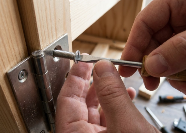
The straight slot also requires suitable screwdriver access. Use a blade that fits the slot and allows the tool to remain aligned. For maintenance or replacement purchases, identify any surrounding components that restrict installation or removal.
Applications
Equipment panels and covers designed for countersunk machine screws.
Furniture hardware with tapped fittings or matching nuts.
General mechanical assemblies requiring a slotted, flush-seating fastener.
Replacement parts purchased against a drawing or existing screw specification.
For furniture applications, identify the threaded connection in the fitting. A machine screw should not be assumed suitable for direct installation into unthreaded wood or sheet metal.
Information Needed for a Quote
DIN 963 reference and required standard edition.
Thread diameter, pitch and overall screw length.
Material designation and required property class or mechanical requirements.
Quantity for each size and configuration.
Surface finish and inspection requirements.
Countersink dimensions, component thickness or assembly drawing.
Matching nut requirements, packing preferences and delivery destination.
FAQ
1.What is the standard reference for this product?
The dimensional and material reference used here is DIN 963:1990 for slotted countersunk head screws. Specify the standard and edition required by your drawing or purchase order.
2.Which materials are included in the reference?
The reference includes steel, stainless steel and brass / copper-zinc alloy. The listed mechanical classes are steel 4.8, 5.8 and 8.8; stainless steel A2-70 and A4-70; and copper-alloy designations CU2 or CU3.
3.What does Product Grade A mean?
It describes dimensional tolerances. It is separate from the material designation and mechanical property class.
4.Does screw length include the head?
Yes. The nominal length is measured from the top of the countersunk head to the screw tip.
5.Is DIN 963 the same as a countersunk tapping screw?
No. DIN 963 is a machine screw for a compatible internal thread or nut. A countersunk tapping screw has a different thread function and should not be substituted by appearance alone.
6.Are all listed sizes available in every material?
The table is a standard dimensional reference. Availability is confirmed for the requested material, grade, diameter, overall length and finish combination.
---
Looking forDIN 963 Slotted Countersunk Machine Screwsfor equipment panels, furniture hardware or general assembly? Send your required material, grade, thread diameter, overall length and quantity toJJ Fastener Factory. Include the countersink or assembly drawing so the quotation can follow your installation requirements.